How it works
Phones, gateways, and radios — connected
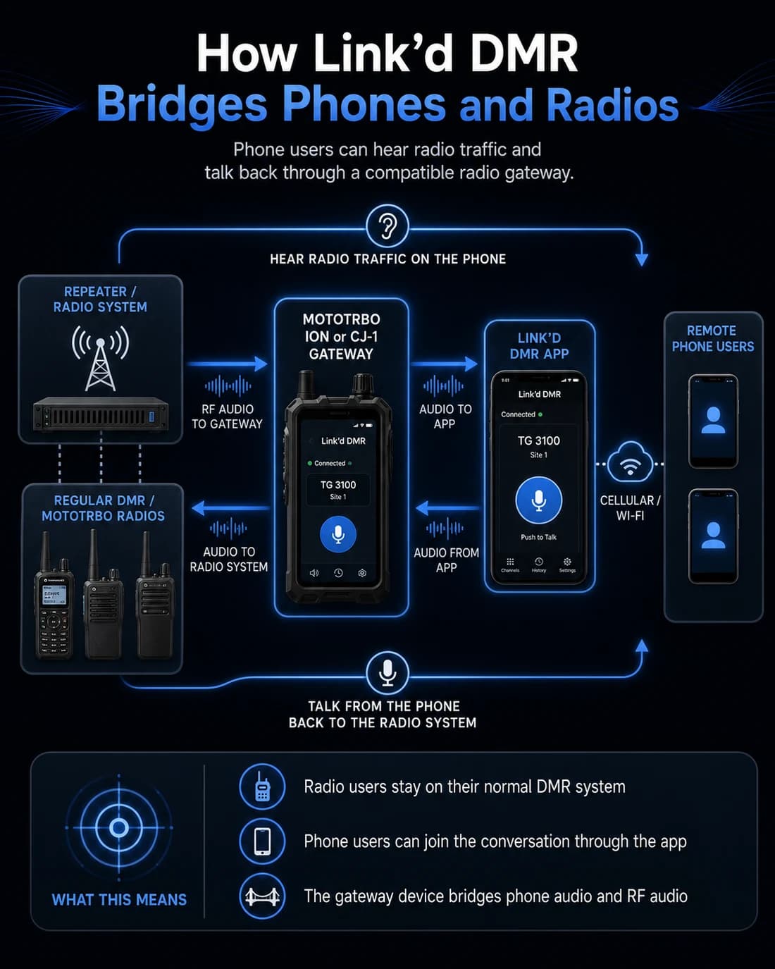
A compatible gateway such as the CJ-1 sits between an existing radio system and Link’d phone users, relaying authorized live audio in both directions.
Radio to phone
A radio user transmits on the configured DMR or analog system.
The supported gateway receives the RF call.
Link’d forwards the authorized live call to connected phone users.
Phone to radio
A phone user presses PTT.
Link’d delivers the live audio to the authorized gateway.
The gateway keys the selected radio channel or talkgroup and retransmits it.
Gateway support depends on the exact device, radio interface, licensing, configuration, and successful hardware validation.
ION gateway concept
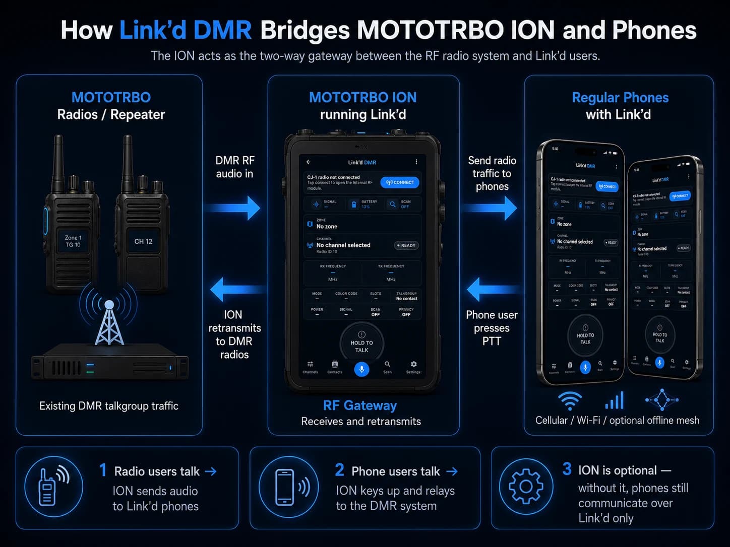
Bridging MOTOTRBO ION and phones
A MOTOTRBO ION running Link’d is one gateway concept under validation: the ION receives DMR RF audio and relays it to Link’d phone users, and keys up to retransmit phone PTT audio back to the radio system. Without a gateway, phones still communicate over Link’d only.
Gateway support depends on the exact device, radio interface, licensing, configuration, and successful hardware validation. Link’d DMR is an independent project and is not affiliated with or endorsed by Motorola Solutions.
Offline mesh
Designed to keep working when coverage disappears
When internet service drops, nearby Link’d phones are designed to keep talking to each other over a local Wi-Fi mesh.
Code68 includes a bounded queue for canned status, check-ins, and assignments.
The included safety model is direct-device and one-hop only.
Entries expire, deduplicate, and require authorization re-checks and explicit receipts.
Nearby stays unavailable until a reviewed production transport adapter is configured.
Multi-hop forwarding, gateway bridging, and verified field range are not claimed in this beta.
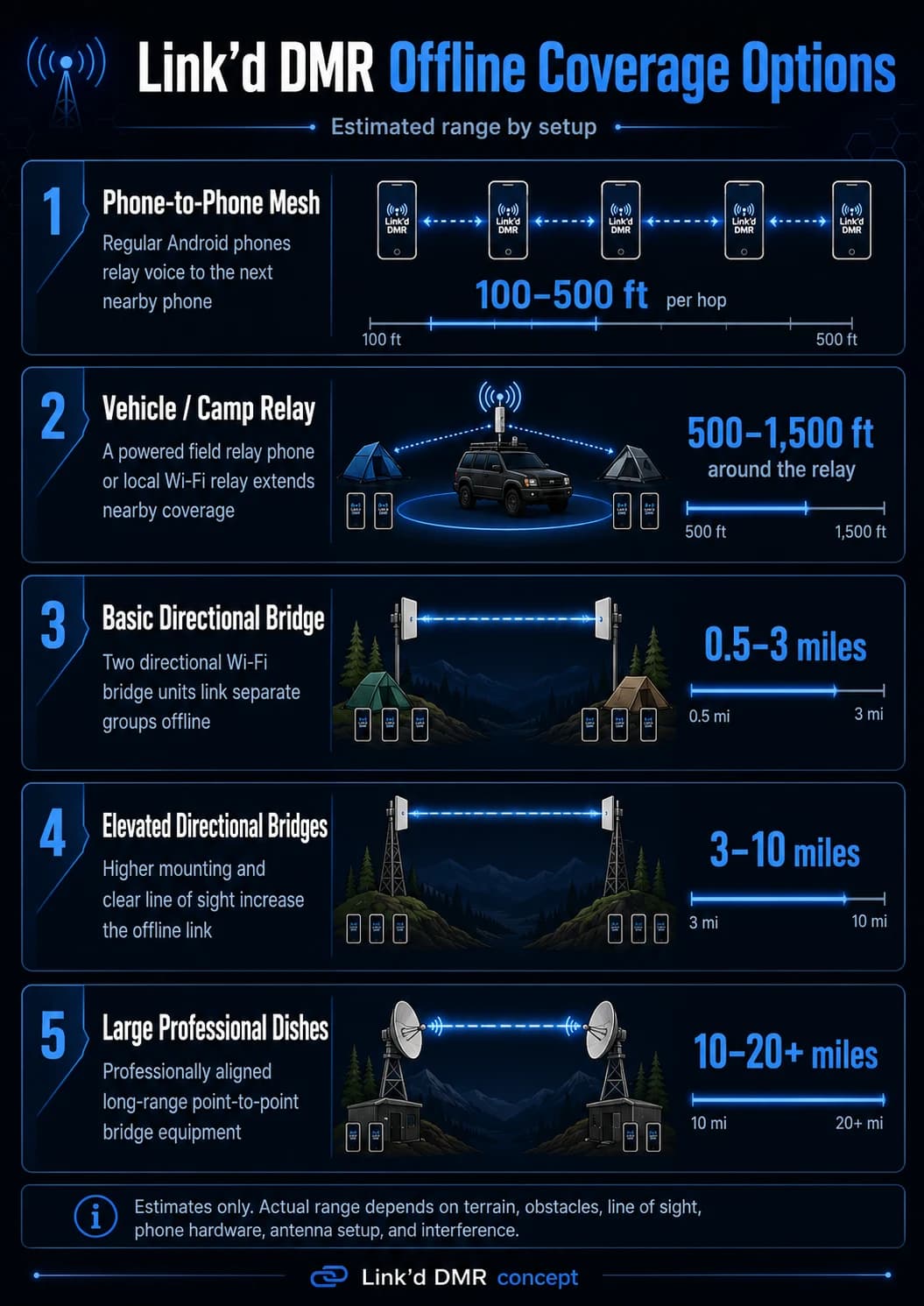
Estimated range
Direct Nearby coordination is included in Code68 but remains unavailable without a reviewed production transport adapter. Link’d does not claim multi-hop delivery or a verified field range; eventual results will depend on terrain, device hardware, mounting, interference, and line of sight.